In this post I will discuss the interaction between SIP and SDP/RTP protocols, with a approach bottom up.
In the beginning a first important note: the Session Initiation Protocol is used ONLY to initiate a session between two endpoints. SIP protocol does not carry any voice or video data (stream) itself, it only allows two or more endpoints to set up connection to transfer that traffic (voice or video) between each other via other protocol, the Real-time Transport Protocol (RTP).
Streaming Audio: the Real-Time Protocol (RTP)
The Real-Time Protocol (RTP) is an application-level protocol that delivers real-time data between two end systems. This is done in such a way that the receiving end system is able to reconstruct the original data stream sent by the other end system, even if the packets are delayed or arrive out of order.
If packets are lost on the way, the protocol will be able to detect this but it does not support requests for retransmissions of any data: every RTP packets contains a sequence number to detect lost and out of order packets.
The reason for not supporting retransmission in the protocol is that it would most likely take too long to request that the source resend the lost RTP packet and for this copy to arrive. A better solution, for the case of audio at least, is to extrapolate sound from previous audio samples to make up for the lost ones, or just ignore the lost data and go on as if nothing has happened (the duration of the audio in one packet is relatively short and the loss of sound for that short period of time will not have a major influence of the quality).
The topic of retransmission is a major reason for not using TCP (TCP protocol, which is a reliable connection oriented protocol, uses retransmissions as a way to guarantee the delivery of the data handed to the TCP layer from the application layer).
Therefore RTP normally uses UDP as the default transmission protocol because that does not provide any reliability features. UDP in turn uses IP, with best effort delivery to encapsulate its data.
Att.: Def. of best effort delivery = Describes a network protocol in which the network does not provide any guarantees that data is delivered.
In the next we summarize the processing and encapsulation of the audio for an IP telephony session before it is sent from a host usng a network connection.
1) The sound from the microphone will be sampled at certain times. A number of samples are bundled together by the application to be the data compressed and encapsulated into a RTP packet. Typically the data related to 20 ms of sound is encapsulated into one RTP packet (to summarize this step: transformation of the voice into a stream of bytes).
2) Every RTP packet is encapsulated into a UDP datagram and transmitted to the destination.
Att.: Does exist several methods how to sample the sound from microphone and compress this stream of bytes obtained: every different methods is a different codec.
The Session Description Protocol (SDP)
The Session Description Protocol (SDP) has three main objectives that need to be achieved before an IP telephony session between a caller and a callee can begin.
First, you need to tell the other party what kind of media you want to receive: audio, video, or both. The second thing is how you want the media to be coded by him so that you can understand what is being sent (what codec is in using). The third thing you need is to inform the other party about what is the address and UDP port you want the media to be delivered to.
For this to work the device on the other side will also have to send you a session description with his information to you, or else you will not be able to send any media data to him. A typical session description looks like the one in the next. SDP is entirely textual !
v=0
o=gptucci 955720785595 955720785595 IN IP4 135.138.242.8
s=Basic Session
c=IN IP4 135.138.242.8
t=955720785595 0
m=audio 2328 RTP/AVP 8 0 96 98 99 97
a=rtpmap:96 SC6/6000
a=rtpmap:98 SC6/3000
a=rtpmap:99 RT24/2400
a=rtpmap:97 VR15/1500
In the next we will see in details the SDP session, but now we can figure out the most important field..
The origin field
o=<username> <session id> <version> <network type> <address type> <address>
The parameters of the origin field will together form a unique identifier for the current SDP session.
The connection field
c=<network type> <address type> <connection address>
The purpose of the connection field is to give to the port number given in the media field (see in the next) an address to be associated with.
The media field
m=<media> <port> <transport> <fmt list>
The purpose of the media field is to let the other party in the session know what kind of media (audio or video) the recipient of the SDP should deliver, to what port on the associated connection address (see above) the media should be delivered to, and in what way the media should be coded. The example of SDP session above uses two standard codecs denoted 8 and 0 in the media field (respectvly PCMA and PCMU). In the same media field are four non-standard codecs, denoted 96, 97, 98 and 99, declared. The non-standard codecs are defined in the following attribute fields, one for each codec number.
SIP
The session initiation protocol (SIP) is a signaling protocol for setting up sessions between clients over a network, i.e. the Internet.
Att.: These sessions do not necessarily have to be Internet telephony sessions: SIP could just as well be used for setting up gaming sessions or for distance learning where a lecture is streamed out to the participants.
The SIP sessions are set up by using a three-way handshake procedure (much like TCP).
When client A (Alice) wants to set up an IP telephony call session with client B (Bob), A sends an INVITE request to B. The INVITE message contains a payload (=data inside the INVITE request) with a description of the session he/she wants to set up with B. If A want to setup an IP voice telephony session, then the session description in payload contains information about audio encoding types A “can understand” and it also specifies on which ports A wants the RTP audio data sent to. The protocol to convey session descriptions is Session Description Protocol (SDP). All the SDP message will be transimmetd inside SIP payload message (it’ll become more clear in the next…) !
When B accepts the call his user agent sends a message with a response code of 200. Any 2xx response means that the message was successfully received, understood, and accepted. In the response client B adds his codec capabilities and the port numbers where he wants A to send his RTP data to (using SDP packet). The final part of the three-way handshake occurs when A sends an acknowledgement to B. By sending an ACK the caller confirms that it has received the response from the callee. After the setup procedure is completed the conversation can begin now using RTP.
SDP in SIP
I have to repeat another time, but it is very important !
SIP protocol is used to initiate a session between two endpoints: it does not carry any voice or video data (stream) itself, it only allows two endpoints to set up connection (using SDP incapsulated in SIP messages) to transfer that traffic (voice or video) between each other via other protocol, the Real-time Transport Protocol (RTP).
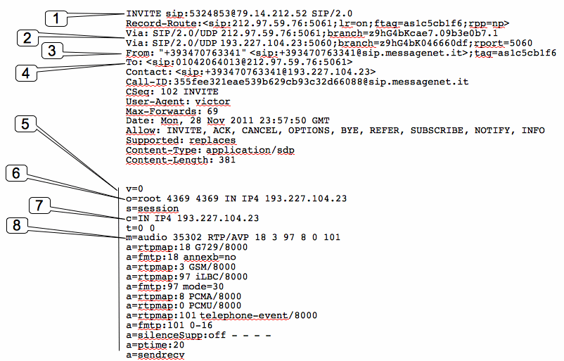
Here is a real example of INVITE message where it is possible to see the structure of the more important SIP message (Alice is calling her friend named Bob).
Att.: In Asterisk it is possible to debug all the SIP messages with the following commands from console.
set verbose 0
set debug 0
sip set debug
1 = This is the SIP Request header that tells us what kind of SIP message this is. This particular packet is a SIP INVITE request for below extension.
532453@79.14.212.52 (calling request)SIP/2.0
Att.: 79.14.212.52 is the ip address of the SIP proxy, more common the IpAddress of the SIP Pbx: 532453 is the Bob’s number.
2 = The Via header contains a list of all SIP proxy servers that this packet has passed through, including the initiating client.
We have see that the SIP protocol can be, and usually is, routed through one or more SIP proxy servers before reaching its destination: it is very similar to how email is transmitted, in that multiple email server are usually involved in the delivery process, each forwarding the message in its original form. Each email server adds a Received header to the message, to track the route the message has taken. SIP uses a Via header to track the SIP proxies that the message has passed through to get to its destination.
Att.: The Via field indicates the path taken by the request so far. This prevents request looping and ensures replies take the same path as the requests, which assists in firewall traversal and other unusual routing situations.
3 = The “To” header specifies the SIP packet’s destination
4 = The “From” header specified who sent the SIP packet
5 = This particular packet is a SDP packet, meaning it contains a Session Description Protocol message that contains information the remote client needs to open an RTP session for this call.
6 = The IP address of the SIP client that created this packet
7 = The IP address the destination SIP client should contact to open an RTP session.
8 = The key pieces of information in this header are audio, 35302 and RTP/AVP. The audio component obviously signifies that this is an audio call, 35302 specifies the port where want to receive the RTP stream, and the IP address is specified in 6: RTP/AVP specifies that the Real-time Transport Protocol will be used for the session. The numbers at the end of this header represent the different codecs that this client supports: the SIP client at the other end must support one of the matching protocols in order to be able to make a successful connection.
More deeply…. The key pieces of information in this header are how the audio will flow from UAS (that receive the INVITE message, and is the called party) to UAC (that transmit this INVITE message, that is the caller).
In the INVITE message we can see the following.
c=IN IP4 193.227.104.23
t=0 0
m=audio 35302 RTP/AVP 18 3 97 8 0 101
These means that the stream related the voice (transmitted by RTP) must be transmitted to ip 193.227.104.23 port 35302.
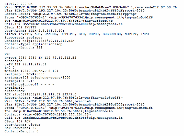
This is the response to this INVITE message.
 In the OK messages there is the information about the other voice stream, related to the flow caller->called.
c=IN IP4 79.14.212.52
t=0 0
m=audio 19340 RTP/AVP 8 101
These means that the other stream related the voice must be transmitted to ip 79.14.212.52 port 19340.
Att.: Usually the stream is transmitted from the same port where the other stream is received.
Alice’s voice is sent from ip 193.227.104.23 port 35302 to 79.14.212.52 port 19340 (Bob’s loudspeaker), and Bob’s voice is sent from ip 79.14.212.52 port 19340 to 193.227.104.23 port 35302 (Alice’s loudspeaker).
Att.: The voice is “transmitted” using bit and a codec: the other party must use the same codec to receive the stream and re-transform the bit-flow to voice. There are different kind of codecs: the number at the end of the header illustrated above (m=audio 19340 RTP/AVP 8 101), i.e. 8 represent the different codecs that client supports (here there is only one codec, but usually we can find more values), and 101 describe other sub-properties about the specified codecs. The SIP client at the other end must support one of the matching protocols in order to be able to make a successful connection. To simplify:
m=<media> <port>/<number of ports> <proto> <fmt>
where proto=codec, and fmt=media format description. Here 8 = PCMA (alaw) and 101 define a paylod type = telephony. All the specified numbers are defined in the IETF RFC related to SDP protocols.
The stream is transmitted using RTP protocol, but all the message that clarify what IP and port using is SDP.
Att.: Unlike SIP, which listens on port 5060 (usually UDP like in Asterisk enviroment, but can be TCP), RTP uses a dynamic port range (and is only ever UDP): in asterisk the default is between 10000-20000 and can be changed using the file rtp.conf.
PREVIOUS POST: From SIP to RTP (Part 1) – Overview
NEXT POST: From Sip to RTP (Part 3) – B2BUA… What ?!


